Posted: Thu Nov 27, 2014 7:21 am Post subject:
Random Chimes Subject description: from random beeps to chimes to singing bowls
I was looking for a simple pseudo-random pattern generator and came up with this random beep circuit. The output almost sounds like morse code, but it isn't. When you look at the wave form output, you will notice that the length of the beeps and the pauses are not that uniform as they should be in real morse code. Both, the gaps and beeps have varying length instead. Nevertheless, the circuit is an interesting starting point to generate pseudo-random patterns. The randomness comes from feeding back the high frequency from the audio oscillator into the shift register input.
Edit: Of course, instead of the 4093 NAND gates, 40106 inverters can be used for the oscillators. I have used the available NANDs because it saves one chip
RandomBeeps.mp3
Description:
Filesize:
334.81 KB
Viewed:
2739 Time(s)
RandomBeeps.PNG
Description:
Filesize:
19.24 KB
Viewed:
1092 Time(s)
This image has been reduced to fit the page. Click on it to enlarge.
Last edited by synaesthesia on Tue Dec 16, 2014 12:28 pm; edited 4 times in total
When replacing the NAND by an XOR and adding a second shift register for the audio frequency, different tones can be produced. This is because the XOR in the feedback path sends the output back either inverted or not. This rotates the current bit pattern or turns the shift register into a Johnson counter. I found at least five different tones being generates this way. I didn't count the silence when all bits are either 0 or 1.
RandomTones.mp3
Description:
Filesize:
496.85 KB
Viewed:
2778 Time(s)
RandomTones.PNG
Description:
Filesize:
24.19 KB
Viewed:
1131 Time(s)
This image has been reduced to fit the page. Click on it to enlarge.
Starting from the random tones circuit above, I added a second short shift register as a tone generator. Each short shift register may generate a pause, or one of the different tones. Again, the tone depends on the clock frequency and the actual bit pattern that is in the shift register. The XOR feedback for each short shift register is controlled this time by one of the outputs from the longer shift register and is changed in a pseudo-random pattern. When the two oscillators are tuned to harmonic frequencies, a nice chime pattern evolves. It is constantly changing because the long shift register is fed back from the result of XORing both feedback signals together, which gives a pretty random input.
RandomChimes.mp3
Description:
Filesize:
953.58 KB
Viewed:
2861 Time(s)
RandomChimes.PNG
Description:
Filesize:
24.05 KB
Viewed:
1179 Time(s)
This image has been reduced to fit the page. Click on it to enlarge.
Taking the idea about the chimes one step further, this circuit resembles the sound of singing bowls. The same principle used in the RandomChimes circuit is used here to generate two oscillators that are are triggered by two signals t1 and t2 and change the generated tone based on the control signals s1 and s2. The outputs of the two shift registers are mixed using a resistor network to generate a triangle waveform. Each of the trigger signals controls a simple VCA using a transistor as a variable resistor. The attenuated signals are finally mixed and amplified by a LM386.
In this circuit the triggers are not random, but are generated from three counter outputs that are decoded into two trigger signals. A rather long 4040 counter has been used to keep the tempo oscillator capacitor small. Three counter outputs are used to generate the trigger signals t1,t2 and control signals s1,s2. The idea was to generate one trigger t1 with a low frequency and a long tone decay, and a second trigger t2 with a higher frequency and a shorter tone decay. The XOR gate U3A is used to shift the faster trigger signal by one clock cycle, so the two trigger signals t1 and t2 are never active at the same time. The 4016 inverter U1D is then used to generate a short pulse for trigger t1, and XOR gate U3D generates a short pulse for trigger t2 on each change of the result from XOR(Q6,Q7). This way it is also guaranteed that the signals s1 or s2 will not change until the next trigger signal occurs.
The recording is using a rather high tempo setting and gives you an idea of the generated tone sequence. As with the previous circuit, the actual tones depend on the content of the shift register at the moment when the control signals change. The resulting sequence thus appears rather random, but follows a constant rhythm.
SingingBowls.mp3
Description:
Filesize:
3.38 MB
Viewed:
2795 Time(s)
SingingBowls.PNG
Description:
Filesize:
48.65 KB
Viewed:
1352 Time(s)
This image has been reduced to fit the page. Click on it to enlarge.
Last edited by synaesthesia on Wed Dec 17, 2014 4:28 am; edited 2 times in total
Joined: Jan 14, 2010 Posts: 6058 Location: Moon Base
Audio files: 728
Posted: Tue Dec 16, 2014 3:53 pm Post subject:
PHOBoS feat synaesthesia Subject description: Drowly
that's another nice circuit
I mixed your recording with some drone sounds from a synth I'm working on, using the arpeggiator in random mode on a slow speed,
and 2 fieldrecordings from The Sounds Found Project. hope you like it .
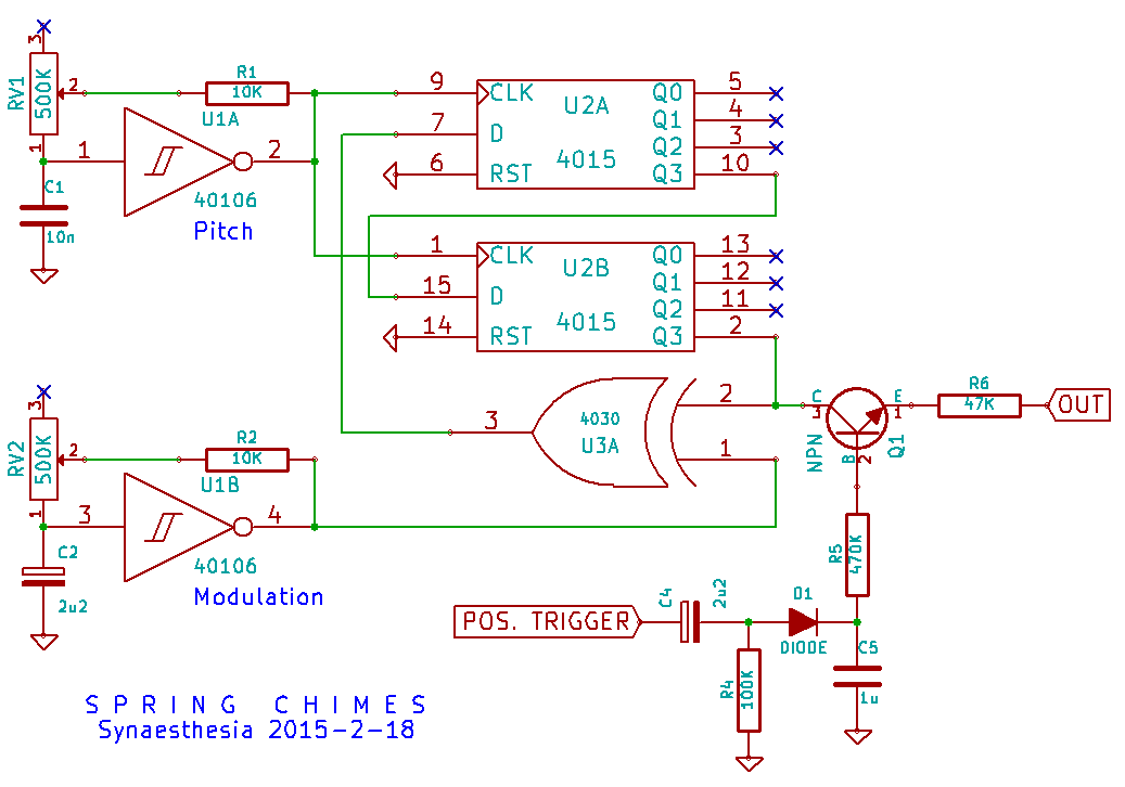
This circuit generates a sound similar to that of a large metallic spring that is plucked. It is based on the same principle as in the Random Chimes circuit. Again, the tones generated vary with the pattern that is rotated either as-is or inverted through a shift register. This generates a range of harmonic frequencies that change with the modulation speed. This time the modulation speed can be increased significantly and a percussive envelope is also applied to the output. Because of the pretty high modulation speed, there wasn't really a need to avoid bit patterns with all 0's or 1's this time.
The recording demonstrates the range of sounds with six example settings of pitch and modulation speed that are played four times each. There are no effects added to the recording. I believe that the slight echo-like timbre comes from the combination of the percussive envelope and the modulated frequencies. I like the metallic sound that the circuit generates.
Spring Chimes.mp3
Description:
Filesize:
896.43 KB
Viewed:
2665 Time(s)
SpringChimes.PNG
Description:
Filesize:
31.02 KB
Viewed:
1055 Time(s)
This image has been reduced to fit the page. Click on it to enlarge.
Joined: Feb 27, 2014 Posts: 26 Location: Redondo Beach
Posted: Fri Feb 20, 2015 2:42 pm Post subject:
very cool...you and phobos are hitting it out of the ball park these days you should get a band together! Last edited by rico C on Sat Feb 21, 2015 9:43 am; edited 1 time in total
Joined: Jan 14, 2010 Posts: 6058 Location: Moon Base
Audio files: 728
Posted: Sat Feb 21, 2015 4:08 am Post subject:
It sounds good XOR's (digital ringmods) are indeed good for metallic sounds which makes me wonder:
have you tried taking the output directly from the XOR gate itself ? (using the transistor VCA)
rico C wrote:
very cool...you and phobos are hitting it out of the ball park these days
I like the designs PHOBoS shares a lot. They are much more suitable for serious electro-music. I am happy if an idea works and uses a minimum number of parts.
PHOBoS wrote:
have you tried taking the output directly from the XOR gate itself ? (using the transistor VCA)
Yes, tried that as well. It is the same signal, only eight clocks earlier. Actually, you can use any output of the shift register to feed it into the VCA.
Interestingly, running multiple outputs of the shift register through a resistor network first does not improve the output, but actually degrades it.
Thanks for sharing these circuits, synaesthesia! I love the SpringChimes! I'm lost in other projects right now, but hope to find the time and breadboard space soon to try some of these out myself.
Joined: Apr 23, 2015 Posts: 184 Location: Perth, Australia
Posted: Thu Apr 01, 2021 10:09 pm Post subject:
Hi NoiseBob, they form a simple envelope generator and VCA.
When you get a 0->5v transition at POS.Trigger it charges up C5 wich allows the transistor to pass the 4015 output to OUT at a volume determined by the voltage on C5 so you get a gong like sound trailing away.
Hi NoiseBob, they form a simple envelope generator and VCA.
When you get a 0->5v transition at POS.Trigger it charges up C5 wich allows the transistor to pass the 4015 output to OUT at a volume determined by the voltage on C5 so you get a gong like sound trailing away.
ooh, that sounds like fun!
i breadboarded the circuit without that part and it does sound quite good already (especially on high speed).. a bit crunchy.
i suppose it can be any type of transistor --- got a box of obscure/old transistors from what i think used to belong to a TV-repair mechanic - including some very specific B&O transistors.
Joined: Apr 23, 2015 Posts: 184 Location: Perth, Australia
Posted: Sat Apr 03, 2021 1:27 am Post subject:
Sounds good, as long as you can identify what transistors you have. You will need an N type and anything over a few tens of milliamps will be overkill. Something like a BC547 is dirt cheap from an electronics hobby store.
Joined: Jan 14, 2010 Posts: 6058 Location: Moon Base
Audio files: 728
Posted: Fri Apr 23, 2021 11:10 am Post subject:
Since the 4015 shiftregisters are just wired in series and only the 8th output is needed a 4021 should work here.
Connect pin 9 to GND, use pin 10 as the CLK input, pin 11 as the Data input and pin 3 as the output. _________________ "My perf, it's full of holes!" SoundCloudBandCampMixCloudTwitchYouTube The Golden Shrimp Guild
Regarding the singing bowls - If I would like to add a manual trigger with a push button can I just connect one of the button terminal to VDD and the other terminal to point t1 (diode anode) ?
Will it work? will it bypass the ongoing triggering of the sound envelope?
Hi R_Gol, not at the anode, but at the cathode. At the anode you would create a shortcut through your switch to the output of the gate when it is LOW. You can use a momentary switch (normally open) safely to send Vdd to the cathode however. If you use a gate instead, another diode would be needed. Maybe add a small resistor when you do so to limit the current for the switch and capacitor a bit. 1K should be just fine.
This modification would bypass the ongoing triggering, and add to it, not supress it.
This modification would bypass the ongoing triggering, and add to it, not supress it.
If I would like to suppress the internal triggering of the two voices and control them both manualy with two different buttons. I can I do so? is it complicated?
another question I have:
What about omitting the lm386 amp circuit and connecting the output to a mixer instead? Do I need to add an op amp buffer? or shall I just connect the 100k resistor and the 47k resistor to the tip of a mono jack?
You cannot post new topics in this forum You cannot reply to topics in this forum You cannot edit your posts in this forum You cannot delete your posts in this forum You cannot vote in polls in this forum You cannot attach files in this forum You can download files in this forum


 Forum index » DIY Hardware and Software » Lunettas - circuits inspired by Stanley Lunetta


 FAQ
 Calendar
 Search
 Memberlist
 Usergroups
 Register
 Profile
 Log in to check your private messages
 Log in
 Chat Room


 .

 you should get a band together!