Joined: Jan 14, 2010 Posts: 6058 Location: Moon Base
Audio files: 728
Posted: Sat Dec 08, 2012 8:51 am Post subject:
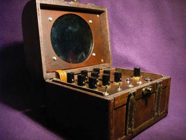
Enneatronic Spectralizer Subject description: 9 oscillator dronebox with hypnotic LED display
RingMad wondered how I achieved the fading on the audio for the Enneatronic Spectralizer so here's
the schematic and some extra info for those interested.
THE ENNEATRONIC SPECTRALIZER
The Enneatronic Spectralizer is a drone box containing 9 tunable squarewave oscillators with a
simple, 1 transistor, VCA section to fade the sound of each oscillator in and out. The same oscillators that
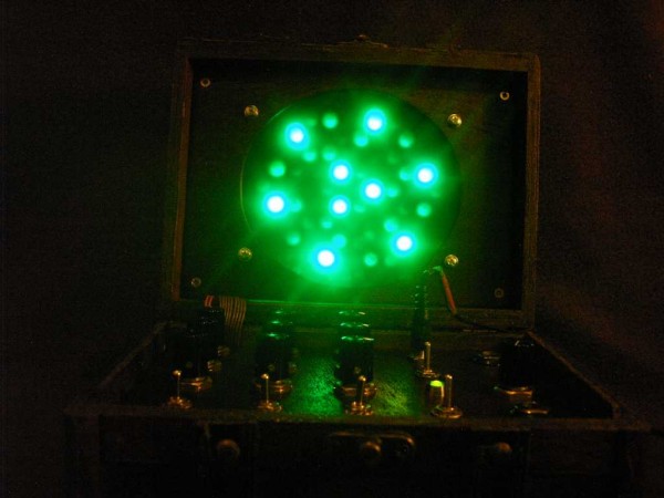
control the VCA's also control 42(!) LED's, arranged in such a way that it creates a constantly changing
display of symmetrical patterns.
thanks for posting that pic richardc64
The oscillators are all made with a CD40106 (3 chips in total) combined with some resistors, capacitors and
transistors to create the fading effect for both sound and LED's. Values were selected by means of experimentation
to get the result I was happy with. So if you want to use the circuit with a different supply voltage you'll probably
have to change some values. The fading of the LED's also varies with the kind of LED's used, so this will need
some experimentation aswell.
Each group of 3 oscillators (build around a single CD40106) also has a switch to turn the sound off. This makes
tuning a bit easier but can also be used to switch between differently tuned drones. The tuning itself is done
with a 47K pot (fine) in series with a 250K trimpot for pretuning (coarse). Originally the circuit was made with
just the 250K trimpots, but it was difficult to tune them pecisely so I added the 47k pots in series and
pretuned them to a low, mid and high section.
The sounds of the oscillators are mixed together with an opamp and then send out to a jack, which is wired up
in such a way that it can also be used as an EFX Send/Return for the build in amplifier. The amplifier itself is a
very basic LM386 setup. The 65Ω speaker was just something I had laying around that was small enough, so it
doesn't have to be 65Ω.
some extra info on the display:
- directly in front of the LED's there's a layer of frosted plastic to diffuse the light a bit. (cut from a box that came with some VHS tapes).
- on top of this is a blue lighting filter to dim the lights. (42 bright green LED's produce a lot of light! )
- followed by a green lighting filter which together with the blue creates a very nice shade of green.
- this is covered with a piece of perspex to protect it which also functions as a mirror if you turn the LED's off (bonus effect).
because there is some space between the LED's and the plastic it creates a sort of 3D effect were the brighter LED's
seem closer then ones that are dimmed. (I added a photo which shows this a bit)
You can find a audio recording of the Enneatronic Spectralizer here
or watch this video to see it in action: edit: uploaded the video directly to the forum
Enneatronic Spectralizer.wmv
Description:
Video of the Enneatronic Spectralizer in action
Filesize:
130.39 MB
Viewed:
1162 Time(s)
PHOBoS - Enneatronic Spectralizer schematic.gif
Description:
Filesize:
67.99 KB
Viewed:
2075 Time(s)
This image has been reduced to fit the page. Click on it to enlarge.
Enneatronic Spectralizer - 06.jpg
Description:
Enneatronic Spectralizer 3D effect
Filesize:
27.89 KB
Viewed:
1210 Time(s)
This image has been reduced to fit the page. Click on it to enlarge.
Enneatronic Spectralizer - 07.jpg
Description:
Enneatronic Spectralizer - perf pr0n
Filesize:
77.2 KB
Viewed:
1121 Time(s)
This image has been reduced to fit the page. Click on it to enlarge.
Wow, PHOBoS, thanks for all that documentation! So very generous of your time.
And let me say, because I'm feeling it strongly right now, that I love these DIY forums here on e-m... so inspirational and educational and fun and it keeps one going knowing there are other people spending hours soldering up crazy projects that most people would not understand the point of.
Joined: Nov 10, 2011 Posts: 878 Location: Lancashire, England
Audio files: 14
Posted: Sat Dec 08, 2012 9:25 am Post subject:
This thing is great ... I was just hypnotised by it for about 5 minutes. _________________ As a mad scientist I am ruled by the dictum of science: "I could be wrong about this but lets find out"
Joined: Jan 14, 2010 Posts: 6058 Location: Moon Base
Audio files: 728
Posted: Sat Dec 08, 2012 1:57 pm Post subject:
RingMad wrote:
people spending hours soldering up crazy projects that most people would not understand the point of.
I think that's a pretty accurate description of me and a lot of other folks here. (and yes, I agree)
JingleJoe wrote:
This thing is great ... I was just hypnotised by it for about 5 minutes.
I forgot to mention, it's like IT's "deadlights", once you watch them it's hard to look away
(and it might drive you insane, but it's probably too late for that anyway) _________________ "My perf, it's full of holes!" SoundCloudBandCampMixCloudTwitchYouTube The Golden Shrimp Guild
Thank you for sharing this. It is helpful as I have been working on a vca type of circuit for my Lunetta and this is proving to be helpful in getting points that I was struggling with working to my liking.
Very cool housing you have created on the last few projects, the LED display on this one makes it that much more interesting.
I forgot to mention, it's like IT's "deadlights", once you watch them it's hard to look away
(and it might drive you insane, but it's probably too late for that anyway)
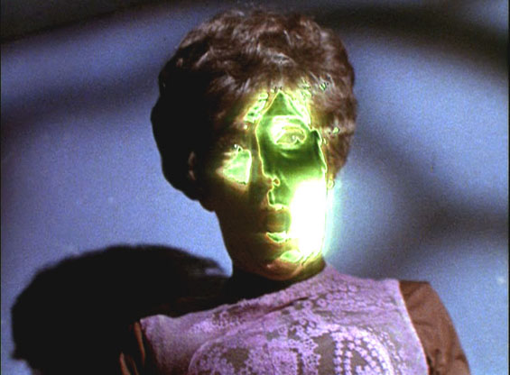
It reminds me of the Neural Neutralizer in the Dagger of the Mind episode of Star Trek (how much of a nerd does that make me?). Hope that it doesn't have the same effect... I really like the sound and look of this. Another thing to add to my list of ideas to try - I don't know if I'll live long enough to get through that list.
dirtyworm wrote:
Thank you for sharing this. It is helpful as I have been working on a vca type of circuit...
Ditto for me. Those single transistor VCAs seem well worth a look at.
Id love to know/see more on how you layed out and wired up the LEDS to the VCAs. It truly is a fantastic effect. The orientation and fade rate is just superb.
Joined: Jan 14, 2010 Posts: 6058 Location: Moon Base
Audio files: 728
Posted: Sun Dec 16, 2012 9:07 am Post subject:
duet for Enneatronic Spectralizer and LED fan
Thanks a lot guys!
nathanxl wrote:
Id love to know/see more on how you layed out and wired up the LEDS to the VCAs. It truly is a fantastic effect. The orientation and fade rate is just superb.
I think I lost the PCB layout for the LED's in a crash else I could post that. but I can tell you that the LED's are wired
in groups of 3 (in the center) or 6.
I should have made a photo before I put the cover in front of the LED's, I'll try to take a photo some other time with the cover.
Actually if you pause the video somewhere around 10-12 seconds you can see the layout, allthough a bit blurred.
here's the first version, with a different layout and no sound. (and cheap chinese LED's )
and here is another recording of the Enneatronic Spectralizer this time droning together with a LED fan
PHOBoS - duet for Enneatronic Spectralizer and LED fan.mp3
Joined: Jan 14, 2010 Posts: 6058 Location: Moon Base
Audio files: 728
Posted: Sun Jun 01, 2014 11:48 am Post subject:
Muied Lumens wrote:
Playing on the radio now - what a gorgeous sound!
Thanks!
Biyi showed interest in making a spectralizer and was asking for a layout and more info so I'll just post that here.
First thing is how the LED's are wired up.
I just soldered them on a piece of perfboard and then soldered wires to the legs to connect everything together.
Here's the layout and a coloured map to show which LED's are wired together and to what knob they are linked.
D1-D2-D3 in series, connected to OSC A1
D4-D5-D6 in series, connected to OSC A2
D7-D8-D9 in series, connected to OSC A3
D10-D11-D12 in series, connected to OSC B1
D13-D14-D15 in series, connected to OSC B2
D16-D17-D18 in series, connected to OSC B2
D19-D20-D21 in series, connected to OSC B3
D22-D23-D24 in series, connected to OSC B3
D25-D26-D27 in series, connected to OSC C1
D28-D29-D30 in series, connected to OSC C1
D31-D32-D33 in series, connected to OSC C2
D34-D35-D36 in series, connected to OSC C2
D37-D38-D39 in series, connected to OSC C3
D40-D41-D42 in series, connected to OSC C3
However I would like to encourage anyone to make a different custom layout, maybe using different colors or combinations,
more or less LED's, LED displays, whatever you can come up with..
Spectralizer LED layout.jpg
Description:
Spectralizer LED layout for perfboard
Filesize:
61.77 KB
Viewed:
781 Time(s)
This image has been reduced to fit the page. Click on it to enlarge.
Enneatronic Spectralizer LED map.jpg
Description:
Enneatronic Spectralizer LED map
Filesize:
196.35 KB
Viewed:
994 Time(s)
This image has been reduced to fit the page. Click on it to enlarge.
Joined: Jan 14, 2010 Posts: 6058 Location: Moon Base
Audio files: 728
Posted: Sun Jun 01, 2014 1:08 pm Post subject:
Enneatronic Spectralizer perfboard layout
Here's the original perfboard layout for the modules
I made 3 of those and later added the 47K pots. I soldered those to the edge of the boards as can be seen on this photo:
(I had to cut a small part off to get them in the box)
The 47K pots are connected instead of the connections between the 250K trimpots and 10K resistors using some wires.
Enneatronic Spectralizer module layout (full).jpg
Description:
Enneatronic Spectralizer module layout (full)
Filesize:
145.21 KB
Viewed:
828 Time(s)
This image has been reduced to fit the page. Click on it to enlarge.
Enneatronic Spectralizer module layout (top).jpg
Description:
Enneatronic Spectralizer module layout (top)
Filesize:
118.27 KB
Viewed:
897 Time(s)
This image has been reduced to fit the page. Click on it to enlarge.
Posted: Mon Jun 02, 2014 8:54 am Post subject:
Enneatronic spectralizer Subject description: Enneatronic Spectralizer
Hi Phobos,thank you very much for all this information!!!! we certainly encourage everyone to help build this fantastic machine.
You really are the master! I expect good hours of entertainment and fun ...
Question: what is the resistor 1k and cap value and what is red circle on top of the circuit? its a led? i think its a led red and the cap its a 100nf on schema..ok?
Thanks again !!! when I have something done .. I will keep you informed.
Dibujo.JPG
Description:
What is the cap value and what is the red circle?led?
Filesize:
28.9 KB
Viewed:
762 Time(s)
This image has been reduced to fit the page. Click on it to enlarge.
Last edited by Biyi on Mon Jun 02, 2014 10:40 am; edited 1 time in total
Joined: Jan 14, 2010 Posts: 6058 Location: Moon Base
Audio files: 728
Posted: Mon Jun 02, 2014 10:34 am Post subject:
The cap is a decoupling cap (I usually don't label those, nor draw them in schematics ) so 100nF would be fine.
And the circle is indeed a (3mm) LED, which simple shows if the PCB is powered, so you can leave that and the 1K resistor off the board.
Hello everyone , this is an approximation of the Phobos Eneatronic Spectralizer. PCBs in pdf, one is the actual view and another the pcb.
I also included the power supply and amplification.
I still have not done the tests to verify them .. I hope to soon! I am now trying to do the pcb for leds ..
Thank you all ..
Phobos I would like to change the name Eneatronic by ....Psychomanteum..
surely add a low pass filter..also.
Joined: Jan 14, 2010 Posts: 6058 Location: Moon Base
Audio files: 728
Posted: Mon Jun 09, 2014 2:38 pm Post subject:
Biyi wrote:
Hello everyone , this is an approximation of the Phobos Eneatronic Spectralizer. PCBs in pdf, one is the actual view and another the pcb.
looks good:)
one small error though, the voltage regulator needs to be a 7810 (instead of 7805)
here's the layout I used.
(I'm working on a blockdiagram which shows how I have things connected)
Enneatronic Spectralizer mixamp layout (full).jpg
Description:
Filesize:
280.92 KB
Viewed:
806 Time(s)
This image has been reduced to fit the page. Click on it to enlarge.
Enneatronic Spectralizer mixamp layout (top).jpg
Description:
Filesize:
253.33 KB
Viewed:
848 Time(s)
This image has been reduced to fit the page. Click on it to enlarge.
Ok guys..pcb,real view and sik components ready to print..for enneatronic, power and amp..enjoy. only remain leds(the must complicate for me...)..surely on perfboard. thanks . Phobos.
You cannot post new topics in this forum You cannot reply to topics in this forum You cannot edit your posts in this forum You cannot delete your posts in this forum You cannot vote in polls in this forum You cannot attach files in this forum You can download files in this forum


 Forum index » DIY Hardware and Software » Lunettas - circuits inspired by Stanley Lunetta


 FAQ
 Calendar
 Search
 Memberlist
 Usergroups
 Register
 Profile
 Log in to check your private messages
 Log in
 Chat Room



 )


 )


 ) so 100nF would be fine.


