Posted: Sun Oct 17, 2010 4:35 am Post subject:
going LFO crazy Subject description: More lfo's please
Damn, I ran out of lfo's on a patch , need to make space for more lfo's .
i need to condense 3 older designed panels to free up space for a new 6 lfo panel i've templated in corel draw.
Panel design for 2 dual vc-lfo's done below and a new module panel design for 6 of Ray's http://www.musicfromouterspace.com/analogsynth/coolnewlfo.html
versatile multi waveform lfo , to be constructed on vero-board & panels drilled in the garden shed .
more pics as i progress .
Dave
old vc-lfos from 2005.JPG
Description:
3 older style single vc-lfo's i built in 2005 plus a 4th board will squeeze into 2 dual vc-lfos
Filesize:
111.78 KB
Viewed:
694 Time(s)
This image has been reduced to fit the page. Click on it to enlarge.
Dual vc-lfo & multi lfo sm.JPG
Description:
2 of the new dual vc-lfo's under construction also multi lfo , which is 6 of Ray's versatile lfo's (a circuit ray has on the website)
Filesize:
140.48 KB
Viewed:
815 Time(s)
This image has been reduced to fit the page. Click on it to enlarge.
It is funny, there are many things in life you can never have too many of. On my list were horsepower, records, chocolate fingers and now LFOs. Most of the time something basic will do, exactly as you are making here!!
I have built 6 of http://www.musicfromouterspace.com/analogsynth/coolnewlfo.html
onto stripboard following the diagram as i go and added the crows nest wiring , also populated a 4th VC-LFO & wired ready for panel assembly , panels are almost ready to dress with sockets & pots , the 3 new design modules will be ready to use for Halloween stream on sunday , They will be ready
6 mfos 'rays new lfo' lfo's.JPG
Description:
Filesize:
193.5 KB
Viewed:
681 Time(s)
This image has been reduced to fit the page. Click on it to enlarge.
CV-LFO no4.JPG
Description:
Filesize:
74.73 KB
Viewed:
694 Time(s)
This image has been reduced to fit the page. Click on it to enlarge.
Joined: Jan 17, 2010 Posts: 193 Location: ithaca, new york
Posted: Wed Oct 27, 2010 6:48 am Post subject:
Nice, i love Ray's cool LFO also and have built quite a few of them. Your stuff never fails to inspire and i have adopted a bunch of your "space saving" techniques into the modules i'm building, great stuff and great sounds from your recent sequencer and SVF threads.
Thanks for the comments guys , i'm probably going to have to review my current capacity on the "windscale" diy power plant for the modular after adding all these upgrades .
6 multi LFO module complete , all working after some head scratching faults / mistakes ......3 stripboard isolator drilled pads had micro slivers of copper shorting (classic 'non concentration'), drill more out , fixed.
forgot 2 wire links , fixed .
Sine wave trimmers all set, & all 6 tested with oscilliscope
as i was wiring i tested some different sizes of caps for the lfo rates i used 100N mylar for the high rate and a Wima 2.2uF box polyester instead of the 2- 10uF electrolytics back to back in the diagram.
I also used Log 100K pots for the rate controls , for me , they give a bit of fine adjustment at the lower speeds.
Dave.
multi LFO.JPG
Description:
Filesize:
89.96 KB
Viewed:
629 Time(s)
This image has been reduced to fit the page. Click on it to enlarge.
6 multi LFO.JPG
Description:
Filesize:
85.36 KB
Viewed:
621 Time(s)
This image has been reduced to fit the page. Click on it to enlarge.
Pots arrived in the post today to finish the VC-LFO's All calibrated & tested , cool .
I found some 10uF non polar caps & have put them in the bottom 2 lfo's low speed switches on the 6 multi lfo module , great for very slow filter sweeps (windy landscape ) .
sounds of 10 lfo modulation to follow ...
MFOS Dual VC-LFO 2010.JPG
Description:
Filesize:
150.57 KB
Viewed:
761 Time(s)
This image has been reduced to fit the page. Click on it to enlarge.
MFOS Multi LFO 2010.JPG
Description:
Filesize:
100.29 KB
Viewed:
644 Time(s)
This image has been reduced to fit the page. Click on it to enlarge.
going through the waveforms and rates on the mfos Multi lfo
Filesize:
1.6 MB
Duration:
1:45
Viewed:
2328 Time(s)
VC-LFO rate sweep by hand.mp3
Description:
VC-LFO rate sweep by hand
Filesize:
742.37 KB
Duration:
0:47
Viewed:
2336 Time(s)
VC-LFO modulated by 2 lfo's.mp3
Description:
2 triangle lfo's from the multi lfo, hooked up to cv1 and cv2 inputs , modulating the vc-lfo at different rates
Filesize:
2.81 MB
Duration:
3:04
Viewed:
2284 Time(s)
super cold wind 10 lfo's - 5 vcf's.mp3
Description:
ice cold north winds , get your thermals on :D..... 3 noise generators hooked up to 5 vcf's , which are being modulated by 10 lfo's (all the new ones) run straight through a vca as an amp
Joined: Oct 24, 2007 Posts: 166 Location: The dark side of the moon
Posted: Fri Dec 06, 2013 2:05 pm Post subject:
Hello Dave,
You might remember me from a while back when I was having a tough time deciding what to build in terms of a synth project. Well, I ended up buying the DIY Synth Experimenter board with the S&H and power supply.
After Christmas I want to start putting things together. The main issue with the Experimenter that I have is that I don't think the oscillators are going to be versatile enough.
I wanted to remedy this by going with the MFOS VC-LFO. I remember you mentioning that this LFO can go pretty high in frequency. I am curious as to what the upper limit is on it. I found your demonstration here where you do a sweep of the LFO, but it doesn't seem to go as high as per your previous description. BUT then I am not sure if there is a range switch on that LFO.
I mainly found this thread because I was looking to see if there were others that have been using multiple LFO's together. Low and behold when this thread came up I recognized the name. I must say I LOVE what you did with that 6 LFO bank of oscillators. I just looked that oscillator up on the MFOS site. So it has a variable waveform skew control, huh? THAT is impressive. It looks like a simple circuit to built too, however, there's no VC ability. Bummer!
Given the circuit design which is based around a quad op amp and half of a 13700, putting two of these LFO's on a board is a given. Going simpler, since these oscillators can't do VC, I don't see too much of a need for the sine wave output. That would eliminate just about half the circuit altogether.
At any rate, I could easily see adding a few of these on a future project...perhaps using that 'Swiss Army Op Amp" board that Ray sells.
Anyway, thanx for uploading those files which gives me a good idea of what these LFO's sound like doing double duty as VCO's.
I think I might buy two VC-LFO boards anyway just to fill out the Experimenter's board I have already.
Scroll down to the first picture you find and that is Dave's synth.
I seriously doubt I would end up with anything THAT big. I think if I DIY something like the Mini Moog and also an Oberheim 8 voice I would be happy for a LONG time.
Joined: Dec 13, 2009 Posts: 847 Location: Israel
Audio files: 18
Posted: Thu Dec 12, 2013 2:28 am Post subject:
Thanks for the link.
WOW, that's a big system!
Dave, your crazy
The problem with big systems is playing with them and never stop, you find your self experimenting all the time and not making music.
I Gusse that's the fun of big systems.
The problem with big systems is playing with them and never stop, you find your self experimenting all the time and not making music.
I Gusse that's the fun of big systems.
Cheers.
Well, for me after many years of trying to play keyboard instruments 'formally', I just have to face it that I just don't have the coordination enough for playing an instrument. So I am actually looking forward to the 'sound design' aspect of working with synthesizers.
As it is my first foray will be the DIY Synth Experimenter, which doesn't have 1v per octave oscillators so it really wouldn't be suited for a keyboard hookup anyway. But I DO want to hook it up to a sequencer and in such a case the 1v per octave isn't necessary.
What I will do though is hook up the synth to my computer so in the event I do create a really cool patch, I can record it into my machine. Then I always could use the patch in midi files.
As it is last night I ordered the components for the PC boards. I bought the Synth Experimenter PCB combo much earlier this year. So I started putting some parts orders together. I started with the PCB components first. I put my first order in with Futurlec as they seem to have pretty good pricing. As for their controls, they only have PCB mount controls and I need solder lug controls. I might end up getting the controls and jacks from Mouser.
Well, I am off, if you like that picture of TONTO, just do a search for it on the web, there is quite a bit of info on the web about it.
The big case i sawed & hammered together in 2005 , 8 years of expansion & tinkering
one module id really love to build is a type of clock distributor in a similar fashion to a module by 4ms company's quad clock distributor http://www.4mspedals.com/qcd.php
Joined: Oct 24, 2007 Posts: 166 Location: The dark side of the moon
Posted: Sat Dec 14, 2013 11:44 am Post subject:
Skrog Productions wrote:
Thanks isak & geo
The big case i sawed & hammered together in 2005 , 8 years of expansion & tinkering
Well, you certainly amassed quite bit in that period of time. For me, though, I have two things working against me, money and space. Being in an apartment that nearly sucks all my money away from me, and trying to feed a family of four, I don't have much money for myself. So I really have to think about what I really need or can use rather that build something that I will only end up using once in a blue moon.
For example, do I really need 3 VCO's, do I need to build a sine wave output on all VCO's? Do I really need two VCA's. That sort of thing. One thing I DO want and probably right on the heels of building the experimenter is the 16 channel sequencer. You might remember I was asking a bunch of questions about that as well.
Hey! You know, since you have the experience with working with these, perhaps you would know what I would really need, some pitfalls to avoid. Etc.
One thing though that I really liked was your multi LFO with skew control that you built here. Since I don't think I would need 6 and two would be enough, that did have me popping the question of converting the experimenter's LFO to this type of LFO. Granted I don't have to do it now as you recommended just building the boards first.
What I am going to do though is add some normalizing functions so this way I don't have to break the bank in getting a ton of patch cords right away. I figured I would turn the Experimenter into some kind half normalled synth like the Ultimate.
Another thing I wanted to ask in regards to patch cords...do you think 1/4" patch cords are better than banana? For one, I could add switched 1/4" jacks that would help out building the normalizing functions. I don't think you can do that with banana jacks.
Quote:
one module id really love to build is a type of clock distributor in a similar fashion to a module by 4ms company's quad clock distributor http://www.4mspedals.com/qcd.php
Cool! That almost seems like it is some kind of frequency divider/multiplier as I mentioned in my other post to you. Would that work in that situation? After all, a waveform IS really a periodic signal such as a clock...or does that unit have an upper limit in frequency?
But yeah, I am just being careful at what I spend and I just want to put something together that I will use. I know many here recommended that I jump right to modules, but I figured that would be more expensive and it certainly would take quite a bit of time before I would get sound out of the synth. Working from an all in one PCB seemed like a better launching point.
Final question (Yeah, I know I am pushing my limit today). The Synth Experimenter doesn't have a faceplate and I know I have to design my own. I do have an art program called Corel Draw but I don't know where to go for all the knob symbols and other labels. So I would be interested in how you put your face panels together.
One of the things I want to do differently in regards to the face panel design is that I want to put all the patch points near the bottom of the synth so this way I will not have a birds nest of wires blocking the controls.
Thanx,
Geo _________________ Lover...I won't take a back seat, tonight. Got some dancin' to do.
Lfo's ..... yes , build the experimenter first , then add a couple of those skew lfo's , vc-lfo's are nice to have , but not essential on a budget sound design synth.
The 16 step sequencer , that will require lots of pots & switches (if you build it cheaply by omitting pots , you'll wish later on you had the full build) , and construction wise ,a big step up from building the experimenter, certianly do-able but time consuming.
An easy option is to maybe get hold of a single channel midi to cv / gate convertor for if you have a midi keyboard & / or cubase or whatever running a midi sequence.
inputs / outputs , i went for 1/4" sockets because in 2005 Rapid UK had a non-RoHS clearout with with sockets going for 5p each , in your design you'll be better going for bannana and use a mini toggle switch to normalise or not.
FACEPLATE........
Since your sound design DIY synth is probably going to evolve in concept and design why not get a cutting of 3mm MDF or ply sheet from a construction waste dump , get the experimenter working and then add small easy extras like wave folders , freq dividers , more lfo's , then when you think no more can be added , finalise a nice bit of aluminium to the final size (2 years later )
Joined: Jan 14, 2010 Posts: 6067 Location: Moon Base
Audio files: 730
Posted: Sun Dec 15, 2013 8:34 am Post subject:
Skrog Productions wrote:
FACEPLATE........
Since your sound design DIY synth is probably going to evolve in concept and design why not get a cutting of 3mm MDF or ply sheet from a construction waste dump , get the experimenter working and then add small easy extras like wave folders , freq dividers , more lfo's , then when you think no more can be added , finalise a nice bit of aluminium to the final size
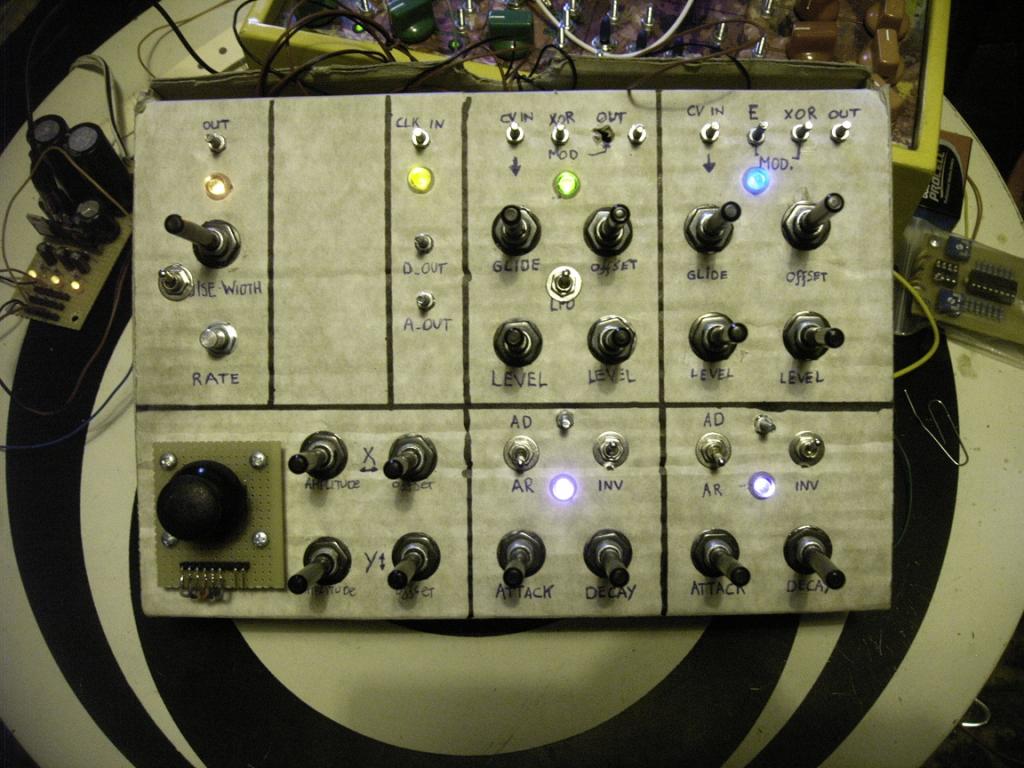
Thick cardboard is also useful for a temporary faceplate, and if you use a box you have also something to encase the PCB's. here's an example:
Using a temporary faceplate is very useful with bigger projects, because it let's you play around with it before it's finished and this
can be helpful to find out how to place the controls in a practical way and what to add or maybe discard.
I use photoshop to design fronts myself, and made my own library with parts. Whenever I have something new I just design it
and add it to the library for future use. _________________ "My perf, it's full of holes!" SoundCloudBandCampMixCloudTwitchYouTube The Golden Shrimp Guild
Joined: Oct 24, 2007 Posts: 166 Location: The dark side of the moon
Posted: Sun Dec 15, 2013 11:40 am Post subject:
Skrog Productions wrote:
Hi
Lfo's ..... yes , build the experimenter first , then add a couple of those skew lfo's , vc-lfo's are nice to have , but not essential on a budget sound design synth.
Well from my readings here it seems to be LFOs are the favored modulation source...even more so than EG's. In fact I have noticed that some EG's (particularly the AREGS) have a repeat trigger function that has the EG retrigger itself making it act very much like an LFO.
I am liking those skew controls LFO's very much though and I do have some stripboards on the way and with some of the extra parts I ordered I would like to try my hand at building a couple of these. As for the VC-LFO's, I was thinking about adding a couple mainly because these can double as a VCO for lower pitches...especially since these do have the sine wave output and they are easier to build than the 1v/octave VCO's. I am kind of putting these off for last given the special parts they need and also the calibration procedure involved. As it is right now I am more interested in making some spacey sounds, drones, etc. If I want something more melodic, I could always use a sequencer...which is the next thing on the block.
Quote:
The 16 step sequencer , that will require lots of pots & switches (if you build it cheaply by omitting pots , you'll wish later on you had the full build) , and construction wise ,a big step up from building the experimenter, certianly do-able but time consuming.
Ahhhhh, my good buddy Dave, I already have a plan for this. A while back I made a thread about this and I was on the fence about going the easy route and going with the 10 step sequencer (or even the simple Baby 10). Early on, these sequencers posed the problem with the odd step number of 10. It would be better just to build it out to 8 channels as that is more musical. Most music is in 4/4 time, so multiples of 4 would work best 4,8,12, 16, etc. Another drawback of the 10 step sequencers is that they use the 4017 Johnson counter and the problem with this chip is that it cannot reverse count. This was one of the main features I liked that the 16 channel sequencer had. So in the end the consensus was to fully build the 16 step sequencer boards but control wise just go with what I needed. So to keep costs down, I figured I would go out to 8 steps first and work with that. Then I could build out accordingly as time/money permits. In addition, there were a couple that mentioned that they never used the fine controls and would have rather used those controls for the new vari-quantizing board. So I figured I would follow suit. I could design a face panel with the spaces ready to go for the full 16 channels, but just put a control in every other spot for a total of 8....likewise with the switches. Then I could build up in stages, going out to 16 channels, then add the Vari-Quantize...all the while I wouldn't have to change the PCB's I started out with.
Quote:
An easy option is to maybe get hold of a single channel midi to cv / gate convertor for if you have a midi keyboard & / or cubase or whatever running a midi sequence.
Hmmmmm, nahhh, that wouldn't be fun. One of the fun things about going the DIY synth route is the hands on work and then all of the knob twiddling and tweaking. I can easily see how much fun a sequencer would be to build and work with. Also I was sold on Thomas White's rotary control panel design which is WAY cool (to say the least). I definitely want that in my rig.
(Incidentally, my wife asked what I wanted for Christmas and at first I was going to have her place the order for my controls, but I have not figured out everything I needed yet, so I ended up having her get me the PCB's for the 16 channel sequencer. YEAH!!! Huh! Huh! )
Quote:
inputs / outputs , i went for 1/4" sockets because in 2005 Rapid UK had a non-RoHS clearout with with sockets going for 5p each , in your design you'll be better going for bannana and use a mini toggle switch to normalise or not.
I am very much on the fence about this as there are pros and cons to both:
1/4" jacks:
Pros - Can normalize, shielded cable (lower noise), premade cables come in nice colors and they are surprisingly cheap.
Cons - Jacks are expensive, they take up more room on the control panel, you cannot piggy back cable outputs to split the signal, you would need special cables for that.
Banana:
Pros - CHEAP!! Take up little space on the control panel. You can piggy back the outputs to split the signal.
Cons - Cables are VERY expensive. You cannot normalize and would have to use a switch. The purchase of the banana in/out AND a switch would kind of negate the 'cheap' advantage above.
I had thought about going hybrid going 1/4" for the audio connections and banana for the control signals. This would eliminate errors in hookup, but it would mean having two different sets of cables. I have not seen this done as of yet, so I am not sure if it is even a good idea.
Quote:
FACEPLATE........
Since your sound design DIY synth is probably going to evolve in concept and design why not get a cutting of 3mm MDF or ply sheet from a construction waste dump , get the experimenter working and then add small easy extras like wave folders , freq dividers , more lfo's , then when you think no more can be added , finalise a nice bit of aluminium to the final size (2 years later )
That is a GREAT idea! In fact taking it one step further, I could use corruplast as a testing panel. Corruplast is corrugated plastic that can be cut by a knife and also holed can be drilled into it. There is a place by me that makes signs and I can get a hold of the stuff pretty cheap. I could cut the material in 5U panels and then make up layouts on Corel Draw. Once I have something, I can print out the paper and stick it to the corruplast and then drill out the holes. I could work with that for a while and it would be easy to add new items, shift things around until finally I have everything into place. Once that is done, then I could make up a permanent aluminium panel for it.
PHOBoS wrote:
Thick cardboard is also useful for a temporary faceplate, and if you use a box you have also something to encase the PCB's.
Granted working with cardboard is faster, but Corruplast came to mind (above) as it is much sturdier and it can be cut with a knife too.
Quote:
Using a temporary faceplate is very useful with bigger projects, because it let's you play around with it before it's finished and this
can be helpful to find out how to place the controls in a practical way and what to add or maybe discard.
Yes, there were things I wanted to change around on the experimenter once I completed building the circuit. One thing I do want to have is a half normalized system in which the VCOs / noise generator go through a mixer through one of the VCFs, and in turn through one of the VCAs. Since there are two AR's and two LFO's. The VCA would have a normaled connection to one AR and one LFO and likewise with the VCA. So that would give me a fully functional synth right from the get go. Then I can come with my cables and play around with patching.
Quote:
I use photoshop to design fronts myself, and made my own library with parts. Whenever I have something new I just design it
and add it to the library for future use.
I am not so lucky. Photoshop very expensive and needless to say permanently out of my spending realm. I have a very old version of Corel Draw that I do most of my work with, so I could use that. I just don't have a good source of the knobs, switch, hole layouts and other parts.
Well, thanx for the information guys.
Edit: I was taking some measurements this afternoon. Wow, the 5U rack standard sure does take up considerable space. My designated spot would only hold 8 modules (5U by 3U). If I replace the shelf in front of me I could squeeze that to 10 modules. The experimenter and sequencer alone would take up most of that space.
Geo _________________ Lover...I won't take a back seat, tonight. Got some dancin' to do.
You cannot post new topics in this forum You cannot reply to topics in this forum You cannot edit your posts in this forum You cannot delete your posts in this forum You cannot vote in polls in this forum You cannot attach files in this forum You can download files in this forum


 Forum index » DIY Hardware and Software » MusicFromOuterSpace.com designs by Ray Wilson


 FAQ
 Calendar
 Search
 Memberlist
 Usergroups
 Register
 Profile
 Log in to check your private messages
 Log in
 Chat Room


 .
 .